The developed ontology provides detailed material information including for what purpose (e.g. interior walls, floors, columns) in the building the material is used. This facilitates the ability to conduct more specific investigations in parts/elements of the buildings. This is useful for assessing how a particular element is contributing to material use in the building and how it can be designed for material replacement (e.g. steel vs. concrete, concrete vs. wood) or material efficiency (e.g. hollow vs. solid columns, above vs. below ground). Utilizing standard construction classification systems also facilitates interoperability with existing uses within construction project management such as costing, estimating, planning and environmental assessment of construction, and suggests a standardized structure for future MI studies.
The dataset provided in this study currently includes material estimates for 70 buildings in North America (i.e. 67 in Toronto, Ontario, one in Winnipeg, Manitoba, and one in Richmond, British Columbia, Canada; and one in New York, USA). 44 of these buildings are single-family dwellings (SFDs). Of these, 40 are proposed new builds for 2020 and 2021, and four are proposed renovations. 18 are mid to high-rise buildings constructed between 1988 and 2020 with one currently under construction. Eight are laneway suites (i.e. Accessory Dwelling Units (ADU) that are located on the same lot with a main dwelling as a detached, semi-detached or other low-rise dwelling26) that are built in between 2019 and 2021. The methods for creating this dataset included three main steps: (1) gathering design or construction drawings for the buildings in the dataset, (2) carrying out material takeoffs to quantify the construction material for each building, and (3) organizing the material data in a construction classifications systems-based database (specifically UniFormat and MasterFormat style). The assumptions made during the material takeoff process and limitations of the study are discussed below.
Gathering design or construction drawings
Design and construction drawings were collected from both public and private sources. Detailed information for the 44 single family homes and one laneway suite were available from the City of Toronto Committee of Adjustment (CoA)27 and were downloaded between July 2019 and July 2020. The building applications available through the CoA website are construction or renovation projects that are applying for variance to existing zoning by-laws, and as part of the application process, details on the proposed construction are posted for public comment. Common reasons for CoA applications include single family houses that are requesting increased building height (e.g. proposed height of 8.51 metres for the permitted maximum height of 7.2 metres), larger driveway width (e.g. proposed driveway width of 10.30 metres for the maximum permitted driveway width of 6.0 metres), or bigger lot coverage (i.e. portion of the lot covered by the building) (e.g. proposed lot coverage of 40% for the permitted maximum lot coverage of 33%). While, by definition, a building requiring CoA is an exception to local planning rules; applications to the CoA are an extremely common step in home construction in Toronto, Canada. In between the years of 2015 and 2019, the CoA received over 3,500 minor variance (e.g. small changes to building setback or parking requirements) applications per year27. Construction drawings for the seven laneway suites and all mid to high-rise buildings were provided by architects, engineers and owners involved in the design and construction of the respective buildings. All construction drawings were either directly exported as Autodesk AutoCAD .dwg files or scanned copies of PDF files that were developed using AutoCAD.
Performing takeoffs for the quantification of building materials
Quantities of construction materials for each building were calculated using material takeoff methods as described in Pratt (2010)28. For the materials used in each building element, the details provided in the schedules and notes in the construction drawings were examined, the dimensions (e.g. length, width, height) of each building element were measured and/or elements were counted from the drawings and the quantities of materials were calculated accordingly. For the details that were not available in the construction drawings (e.g. bricks, stones, mortar, I-joists) external sources of information, such as local and national building codes and product brochures, were used. In addition, industry experts, such as structural engineers and estimators, were consulted for advice on building design practice, particularly for estimating the rebar ratios of mid to high-rise buildings. Drawings of the newly proposed SFDs were imported to Autodesk AutoCAD 2020 to measure the lengths and areas of each construction material for each building element. Drawings of the renovated buildings, laneway suites and mid to high-rise buildings were exported to the On-Screen Takeoff (OST) tool29, and OST (v 3.96.00.23 and v 3.98.2.39) and AutoCAD (Q.47.0.0 AutoCAD 2020) were used in parallel. The research team also investigated the use of 3D models, such as Building Information Models (BIMs), as an alternative takeoff process, however, the elements that are usually omitted in BIMs (e.g. reinforcement bars), the level of detail of the models in current practice and the reality that models are often developed and used for earlier stages of design (and often do not reflect the final building) currently present a challenge in terms of facilitating the quality and detail of data presented in this study. The details, measurements and calculated volume and mass of each construction material were recorded in Microsoft Excel spreadsheets. Details of the material takeoff process and the characteristics of the buildings included in the dataset are described in the Technical Validation section.
Creating a construction classifications systems-based database
A database structure was developed using UniFormat and MasterFormat24,25 for recording the materials (e.g. concrete, steel, masonry) and determining for what purpose the material is used in the building (e.g. substructure, superstructure, floors, walls). The two classifications complement each other24: UniFormat subdivides a facility by functional building elements, and MasterFormat subdivides it by the materials used. Where insufficient specification exists within Uniformat and MasterFormat to clearly identify the building element and material; additions were made (more detail in online-only Table 1 below).
UniFormat (A Uniform Classification of Construction Systems and Assemblies) is mainly used for cost estimates and organized in a way that arranges construction information based on the functional characteristics of building elements which are physical parts of a facility (e.g. shell, superstructure, substructure)24,30. The original UniFormat classification was developed jointly by the General Services Administration (GSA) and the American Institute of Architects (AIA) in the early 1970s. The latest version of UniFormat was published in 2010 and is referenced in this study. MasterFormat is used as a specifications-writing standard for organizing construction information for commercial building design and construction projects in North America25,30. MasterFormat is focused on construction products and activities, and divides a building in terms of the related results achieved in a stage of construction (e.g. production, maintenance, demolition), which can be identified by the construction resources used (e.g. concrete, metals, wood), or the trade that was involved (e.g. earthwork, masonry)24. It has been used in bidding and specifications since 1960s25,30 and the 2020 version of MasterFormat is referenced in this study. Both UniFormat and MasterFormat are used to arrange and organize building information throughout the whole life cycle of buildings (i.e. planning, design, construction, operation, and maintenance), and this work makes use of the design and construction modules.
UniFormat has nine categories (i.e. A-Substructure, B-Shell, C-Interiors, D-Services, E-Equipment and Furnishings, F-Special Construction and Demolition, G-Building Site Work, and Z-General) further divided into four hierarchical levels (Levels 1 to 4) with increasing specificity of purpose24. An example breakdown of an element can be: Shell (Level 1), Superstructure (Level 2), Floor Construction (Level 3), Floor Structural Frame (Level 4). An additional Level 5 is added to UniFormat in this study to specify some structural elements in the takeoff that would otherwise be unclear (e.g. floor girders and beams) (more detail in online-only Table 1 below). With the focus on building material quantities, this dataset and data structure is so far limited to six Level 1 categories: 1) Substructure, 2) Shell, 3) Interiors, 4) Services, 5) Sitework, and 6) Special Construction and Demolition:
-
Substructure includes the foundations, slabs-on-grade, and subgrade enclosures,
-
Shell includes superstructure elements and exterior enclosures,
-
Interior consists of elements such as interior construction and interior finishes,
-
Services include the components such as conveying, heating, ventilation, and air conditioning (HVAC),
-
Sitework includes site preparation and improvement works, such as roadways, parking lots.
-
Special Construction and Demolition includes special facility components, such as pools, and special function construction, such as sound and vibration control.
MasterFormat includes 44 Divisions, each representing a particular trade, or the construction resources used in a building25. The database structure presented calls on eight of these divisions, namely 3-Concrete, 4-Masonry, 5-Metals, 6-Wood, Plastics, and Composites, 7-Thermal and Moisture Protection, 8-Openings, 9-Finishes, and 32-Exterior Improvements. These are the divisions dealing with the description of building materials that were quantified. Other divisions dealing with facility services (e.g. plumbing, HVAC), site and infrastructure (e.g. utilities) and process equipment (e.g. pollution control equipment) were not used for describing the building materials studied in this work. Under each division, MasterFormat provides more categorization based on the nature of the related construction work. For example, there is a Cast-in-Place Concrete category under the Concrete division; it is further divided into Concrete Finishing, then Polished Concrete Finishing, followed by Polished and Dyed Concrete Finishing sub-category. In the database, the top-level divisions, such as Concrete, are named Level 1 and the further subcategories are named MasterFormat Level 2 to 5 (e.g. Cast-in-Place Concrete Level 2, Concrete Finishing Level 3, Polished Concrete Finishing Level 4, and Polished and Dyed Concrete Finishing Level 5), where applicable. Level 5 in UniFormat and Level 5 in MasterFormat do not exist for every building material. In our data structure, Uniformat Level 1 to 4, and Masterformat Level 1 are mandatory (i.e. they require a value to be entered). The other sublevels are optional and can be used to communicate more specificity on the building element or material. In the dataset, all materials have at least Level 1 through 4 in UniFormat, and most of the materials have Level 1 through Level 3 in MasterFormat.
As explained above, each building material in the database is categorized by UniFormat levels (e.g. Substructure, Foundations, Standard Foundations, Wall Foundations, and Continuous Footings) and MasterFormat levels (e.g. Concrete, Cast-in-Place Concrete, Structural Concrete, and Lightweight Structural Concrete) to describe its function and material, respectively. Accordingly, details of each building’s construction are finely recorded with increasing detail through the use of nested levels. Through aggregation to a higher level, the data structure allows aggregation for material (e.g. amount of concrete, or cast-in-place concrete, or structural concrete, or lightweight structural concrete), for function (e.g. substructure, or foundations, or continuous footings) and a combination of both (e.g. amount of lightweight structural concrete used in the substructure, or amount of concrete used in the foundations).
Figure 1 demonstrates how buildings and data entries are coded within the database and a sample approach for aggregating by material and function. This example is for a sample data record (i.e. 016_CA_TOR_00IFC_2021_SND_B01_A1010.10.0CF_032113.00_KG_2) that corresponds to the amount of concrete reinforcement in the continuous footings of one building. More specifically, this is a record of the amount of galvanized reinforcement steel bars used in the continuous footings of the case study building number 16 that is expected to be completed in 2021 in Toronto, Canada, and shows that this information is based on the issued for construction drawings. This example data record has an uncertainty score of 2, meaning that the material quantification is based on the original building drawings and details (e.g. specifications, notes, legends). In addition, for each building, the related gross floor area (GFA) of the building (i.e. 613.38 m2) is included in the data record, along with the amount of construction material that was calculated through material takeoff (i.e. 1,393.68 kg). Figure 1 illustrates the variables in each record and the tree diagram shows how this information is stored within the database structure. The structure is designed to facilitate simple data exploration, collation and analysis using computer code. Sample exploratory codes are included in the data repository14,15 which include calculations of material intensity in a building and queries on material uses for specific functions in buildings as well as the average amount of material used in a particular type of building (e.g. apartment buildings, single family dwellings) in a particular part of the building (e.g. interior, exterior, below ground). The sample code also shows how each building element category described in UniFormat contributes to the total material intensity. Sample calculations are also provided to calculate further descriptors of the buildings, for example a building’s climate zone based on its location and the number of floors relative to the ground (e.g. above ground, ground, below ground and roof).
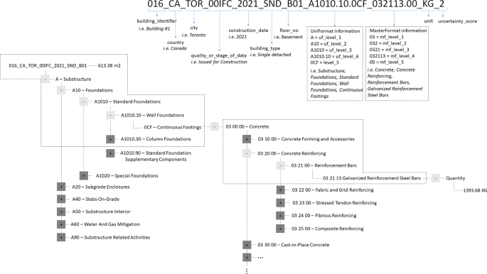
Sample data record 016_CA_TOR_00IFC_2021_SND_B01_A1010.10.0CF_032113.00_KG_2 and its tree view.
Below is the detailed explanation of the variables for the data records in the database. A data record that consists of a code that has fifty-seven digits is created for takeoff within each building. The variables are detailed below, each of which are separated by an underscore (_) in the data record code:
-
building_identifier is the first three digits in the data record code and is unique for each building in the dataset (e.g. 001, 002, etc.).
-
country (two digits) is the country where the building is located. ISO 3166–1 alpha-2 code31, the two-letter country codes defined in ISO 3166–1, is used to identify the country name in the database structure.
-
city (three digits) is the city where the building is located. The first three letters of the city name are used to represent the city in the database (e.g. TOR for Toronto). When new city names are added in the database, users should ensure they are using a unique identifier with their country. If the first three letters are already taken, users should choose other letters from the city name.
-
quality_or_stage_of_data (five digits) communicates the quality or stage of building drawings, demonstrating the level of completion of construction documents, such as Issued for Construction (00IFC) or Issued for Building Permit (0IFBP).
-
construction_date (four digits) is the year (or projected year) of completion. For renovated buildings, construction date is the year the building was originally constructed.
-
building_type (three digits) shows the type of building that is quantified (e.g. single detached (SND), commercial (OFF), institutional (INS)). “R” in the building type code indicates that the material takeoffs were completed from drawings during renovation of the building (e.g. SNR for renovated single detached house).
-
floor_level (three digits) describes the floor or part of building where the material is placed. The code designated for roof is 00R, while 999 represents the whole building, for example in the case of cladding materials covering the surface of the building. Underground floors are named based on purpose of use (i.e. basement or parking), and basement is denoted with letter B (e.g. B01) while parking is denoted with letter P (e.g. P02). Foundation is 00F, ground floor is 000, mezzanine floors are denoted with letter M (e.g. M00), and above-ground floors are 002, 003, etc.
-
UniFormat information is represented with the next 12 digits in the data record code. The first digit is the uf_level_1 code, and it is followed by two-digit uf_level_2 code, followed by two-digit uf_level_3 code, followed by a dot, followed by two-digit uf_level_4 code, followed by a dot, and followed by three-digit uf_level_5 code, or 000 if there is no Level 5.
-
For example; A1010.30.0SF (A = Substructure = uf_level_1, A10 = Foundations = uf_level_2, A1010 = Standard Foundations = uf_level_3, A1010.30 = Column Foundations = uf_level_4, 0SF = Spread Footings = uf_level_5).
-
-
MasterFormat information is the next nine digits in the data record code, first two digits being the mf_level_1 code, followed by one digit mf_level_2 code, followed by one-digit mf_level_3 code, followed by two-digit mf_level_4 code, followed by a dot, and followed by two-digit mf_level_5 code, or 00 if there is no Level 5.
-
For example, 033116.00 (03 = Concrete = mf_level_1, 033 Cast-in-Place Concrete = mf_level_2, 0331 = Structural Concrete = mf_level_3, 033116 Lightweight Structural Concrete = mf_level_4, 00 = mf_level_5).
-
-
The next two digits of the data record is the unit. For each data record, the amount of construction material that was calculated via material takeoff is expressed in terms of mass (i.e. kg). Two quantities are reported for each material takeoff, a minimum and a maximum. For materials where direct measurements were possible (e.g. a concrete column) or only one value was available (e.g. composite decking dimensions from a brochure) the two values are the same and represent a discrete number. For quantities calculated through assumptions (e.g. the percentage of steel rebar which was based on expert elicitation) the minimum and maximum are different and reflect some of the uncertainty in the estimate.
-
uncertainty_score (one digit) communicates the uncertainty of the data sources used in the quantification of the material on a scale of 1 to 6 (more detail in online-only Table 2 below).
-
For every building, Gross Floor Area (GFA) information is stored in the database. The GFA is the total floor area of all floor levels including the underground space, and contains the area taken by external walls, internal walls, columns, and partitions. The unit of measurement for the GFA is square meters.
Although UniFormat and MasterFormat have long been used in practice in construction project management and costing, there were some adjustments and additions needed to facilitate a clear description of what functions the materials serve in each building. Online-only Table 1 summarizes the changes made. Additions were kept to a minimum to retain the advantages of interoperability with other uses of UniFormat and MasterFormat. Specific changes made are: UniFormat Level 5 is added to specify the structural element that is subject to material takeoff (e.g. column supporting floors), and a new Level 2 category and its related subcategories to UniFormat are added to classify the below-grade interior elements that are not part of the foundation and distinguish from above grade internal walls (Online-only Table 1).
Assumptions made during the material takeoff process and limitations
During the material takeoff process, data were compiled from drawings made by different firms with different levels of detail. In some cases, this necessitated using additional indirect data sources such as local building codes, as further explained in online-only Table 2 in the Technical Validation section. Similarly, if direct measurements were not provided on the drawings, dimensions of building elements were scaled off the drawings which reduced accuracy.
Due to the large amount of material in mid to high-rise buildings, the scope of the material takeoff in these cases has been limited the major structural elements, and cladding elements when there was enough detail available in the drawings to facilitate cladding takeoffs. This meant a focus on concrete and steel, and wooden elements in the case where the framing of the building is timber. These represent the majority of materials in such buildings4. The scope includes all the concrete within the building footprint and excludes concrete finishing, smaller architectural concrete detailing, and for some buildings, temporary works used to support excavation. For steel, bulk structural steel was estimated, which includes steel decks, most rebar, steel members; while exclusions include structural connection details and anchor bolts, block wall rebar, composite deck rebar, stair rebar, metal grates, steel from shoring, MEP hardware, fittings, furnishings, and architectural features. For smaller buildings (e.g. SFDs and laneway suites), the quantification of materials includes structural members, envelopes, interior partitions, and excludes all materials used for mechanical and electrical services, architectural detailing for exterior walls, and furnishing.
Across the dataset, the drawings were prepared by different companies with different styles of presentation and detail. In particular, the material takeoff process of the renovated buildings was more challenging, due to changes in building codes between time of initial construction and studied renovation, and the potential for additional unrecorded past renovations. For the renovated buildings, the original year of construction is recorded in CoA documents, and the extent of the current renovation is known. In some cases, determining if a building element was new or original was ambiguous (for example: windows). There were also some building elements not shown on the available drawings (e.g. floor sheathing, exterior and interior wall structure, roof structure). In these cases information (e.g. dimensions, spacing) were estimated from either the Ontario Building Code (OBC) or the National Building Code (NBC) and the assigned uncertainty score adjusted accordingly.