The materials and methods concern two areas. The first area is the materials and methods related to the printed measuring instruments made via Fused Filament Fabrication. The second area of interest is the bulk material (regolith) used to test the produced measuring instruments. The subsection of Bulk Material Tests describes all the tests related to examining the performance of the 3D printed measuring instruments, of the 3D printed measuring instruments in combination with original stainless steel components, and of original stainless steel instruments.
Fused filament fabrication printed equipment
The measuring instruments were printed by fused filament fabrication (FFF) 3D printing technology on a Prusa i3 MKS3 printer (Praha, Czech Republic), which is shown in Figure 1a. PLA and ASA filaments manufactured by Prusament were used. ASA filament is the successor of ABS filament with superior properties, such as UV stability, high impact resistance, wear resistance, and easier printability for FFF printing method24.

(a) Prusa i3 MKS3 printer with FT4’s 3D printed blade and vessel; (b) Schulze’s S size shear cell with lid (from top to bottom–aluminium, 3D CAD by Autodesk Inventor 2021, 3D printed); (c) Schulze’s shear cell sliced in PrusaSlicer version 2.3.0. This figure was created in Gimp 2.10.32.
The Prusa i3 MKS3 printer uses G-code numerically controlled machines, which allows users to provide instructions telling the motors where to move, how fast to move, what path to follow and how fast to feed the filament. Before creating the G-code, a 3D CAD model of the original is created that could be 3D printed as shown in Figure 1b. The G-codes for the prints were sliced in PrusaSlicer version 2.3.0 with the layer height of 0.20 mm as shown on Figure 1c. The infill for all the parts had different infills that are shown in this section. The infill pattern was chosen as gyroid except for 100% infill, which is forced to be rectilinear. The PLA instruments were printed at an extrusion temperature of 210 °C and bed temperature of 60 °C. The ASA instruments were printed at an extrusion temperature of 260 °C bed temperature of and 110 °C.
For the Schulze’s RST-01.pc (RST) tests, we used a set of shear cell and lid from different materials (original aluminium, PLA printed, ASA printed). RST tests are described in the following subsection Bulk Material Tests.
For the Freeman’s Flow Tester 4 (FT4) tests, we used a 85 ml measuring sample vessel as an assembly of parts that will contain the sample powder during measurements. The 3D printed sample vessels and instruments were printed from PLA and ASA filaments. These printed instruments required design modifications to withstand mechanical loads. The printed vessels were either all printed or were partly 3D printed and also comprised of original components, such as compression piston and blade manufactured from stainless steel. Overall, we used a set of specimens (original stainless steel, PLA printed, ASA printed) and their combinations (original vessel with a PLA blade, original vessel with an ASA blade, PLA vessel with an original blade, and ASA vessel with an original blade). FT4 tests are described in the following subsection Bulk Material Tests.
Fused filament fabrication (FFF) 3D printing technology creates parts layer by layer. A consequence of layering is the presence of pores and heterogeneities that cause anisotropic behaviour and preferential crack orientation25. The resistance of parts to mechanical damage is dependent on the orientation of the deposited layers26,27,28. Thus, the orientation of the parts on the 3D printer bed is an important consideration when manufacturing components29,30,31. The orientation of the measuring instruments was chosen accordingly as shown on Figure 2., and the design modifications have been made to the measuring instruments to prevent damage due to mechanical loading. The Figure 2 is illustrative to show layering of the parts from the bottom up and the picture does not show support material, support material interface, skirt, bridge infill, and overhang perimeter. The layers are stacked from the bottom up. The Figure 2a shows Schulze’s small ring cell, lid, and driving pins. The Figure 2b shows layering of the FT4’s bottom part, upper part, and funnel. The Figure 2c shows layering of the FT4’s shaft with the nut, shear head, blade, and vented piston.

(a) The layering of the Schulze’s small ring cell (S size), lid, and driving pins; (b) the layering of the FT4’s bottom part, upper part, and funnel; (c) the layering of the FT4’s shaft with the nut, shear head, blade, and vented piston. Layering was generated by PrusaSlicer version 2.3.0. This figure was created in Gimp 2.10.32.
The Schulze’s small ring cell (S size)32 was printed with bottom plate as one piece. Three pins with interference fit were printed separately to rotate the cell by driving axle. The Schulze’s lid matching small ring cell was printed as a single piece. The shear bars32 were thickened from 1 to 2 mm and no screws were used. The design of the original, the 3D modelled, and the PLA fabricated shearing cell with lid are shown in Fig. 1b. The weighed parts, the weighed printed parts with supports and their infill percentage used in printing are shown in Table 1. The original aluminium shear cell weighed 728.4 g and the original aluminium lid with stainless steel shearing bars weighed 235.4 g. The PLA printed parts weighed 2.6 times less, and the ASA printed cell weighed almost 3 times less than the original parts. Infill used for all Schulze’s printed parts was 100%. The differences in weight are due to different material densities. Aluminium has a density of 2.7 g.cm−3, PLA filament has a density of 1.24 g.cm-3, and ASA filament has a density of 1.07 g.cm−3.
The 3D printed FT4 measuring set and the original measuring set are shown in Figure 3b and c. FT4’s sample vessel is originally made from five pieces, which were reduced to two parts. The 3D printed bottom part has replaced 85 ml vessel with an inner diameter of 48 mm, its removable bottom, the holder that keeps it in place during measurement, and rotational holder for top part. The 3D printed upper part replaced for the upper 85 ml vessel with an inner diameter of 48 mm and it is pivotally seated on the bottom part. The original vessel assembly of two 85ml vessels with a removable bottom, a holder that keeps the whole vessel in place during measurement, and rotational holder for the upper part weighed 291.8 g. The original vessel assembly for angle of internal friction measurement differed by having a removable bottom for internal friction and weighed 289.9 g. Vessel assemblies printed from PLA for compressibility and internal friction measurements weighed approximately 3 times less than the original assemblies. The ASA printed vessel assemblies weighed more than 3.3 times less than original assemblies.
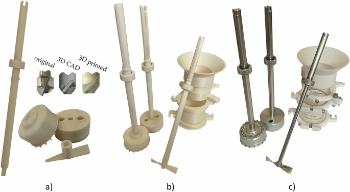
Design of FT4 instruments (a) FT4’s printed shaft, blade, vented piston, and shear head; (b) PLA printed FT4’s measuring set; (c) original FT4’s measuring set. This figure was created in Gimp 2.10.32.
The 3D printed funnel had a reduced height, which does not affect the measurement. The original funnel is made of plastic and weighed 30.7 g. The PLA printed funnel weighed 25.8 g, and the ASA printed funnel weighed 22.2 g.
The FT4 measuring instruments such as the shear head, blade, and vented piston, were 3D printed in two parts. The first part was the shaft with the nut, which was the same for all three measuring instruments. The shaft was connected to the second part by end of a square cross-section shaft (Figure 3a). This shaped connection transmits torque without the two parts of the measuring tool rotating against each other. The manufacturing precision of the FFF printing method created a slight overlap that allowed the two parts to be joined by hand but did not require protection against ejection. The shaft infill was chosen as 7% to overcome the warping during printing with ASA filament. The infill setup improves geometric dimensions and tolerances, such as radial runout and total run out of the shaft. The second parts of the blade, the vented piston, and the shear head were printed with 15% infill setup. Design modifications to the instruments were made to prevent damage due to mechanical loading, the shearing bars of the shear head were thickened from 0.1 to 0.8 mm, and the blade was thickened from 0.7 to 1.8 mm. The 3D printed shear head was printed as one piece, so the screws were not used in the design. The blade was further modified to ensure similar forces and torques during conditioning of the measured samples. The curvature of the blade had less bending, resulting in a smaller angle at each end of the blade (Figure 3a). The original blade had the end of the blade curved at an angle of 70 degrees, while the end of the 3D printed blade is only curved at an angle of 40 degrees.
The price of 3D printing has its benefits. The material for 3D printing (PLA and ASA) is approximately 3 times more expensive compared to aluminium or stainless steel per kilogram. However, 3D printed instruments are 2.5 to 10 times lighter than the originals. After accounting for productional waste, the difference in material weight is even greater. The costs diversify depending on the cost of machining, complexity of machining, need to change machining tools. In contrast, 3D printing is more versatile, simpler, and with lower weight of the final product. The productional costs of the original instruments are at least 30 times higher than for 3D printed instruments.
Bulk material
Regolith is a terrestrial term which is also used to refer to materials on other celestial bodies. Nowadays, it is used as a common expression for a layer of fragmental rock material. The formation and evolution of regolith is a complex process. In the formation of lunar regolith, two basic mechanisms have been determined. Firstly, destructive, which is the excavation of existing regolith by impact crater, and secondly, constructive, which is the addition of new layers. These processes cause very wide structural and stratigraphical differences in regolith, even between locations only few meters apart11.
Lunar regolith simulant powders are terrestrial based on samples analysed by experiments carried out directly on the Moon, or remotely monitored from Earth11. As mentioned above, materials used in this study are two lunar regolith simulants. These two powders were made by the CLASS Exolith Lab. The simulants, shown on Fig. 4a, are made from natural terrestrial materials in a terrestrial environment, and thus not all properties of lunar mare simulant (LMS-1) and lunar highlands simulant (LHS-1) may be copied. The producer guarantees properties such as mineralogy, bulk chemistry, and particle size distribution. However, particle shape, reactivity, oxidation, and weathering are poorly simulated properties in the simulants.
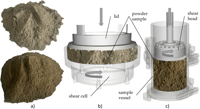
(a) Lunar regolith simulant LHS-1 (above) and LMS-1 (bottom); (b) Schulze’s shear test setup; (c) FT4’s shear test setup. This figure was created in Gimp 2.10.32.
Although the particle size is guaranteed by the manufacturer to be between 0 and 1 mm, a granulometric analysis was carried out. Cilas 1190 laser analyzer (Cilas, Orleans, France) was used to measure the particle size distribution by the Fraunhofer diffraction method31. Water was used as the measurement medium because neither LHS-1 nor LMS-1 dissolved in water. Sonication was used during the measurements to ensure complete dispersion of the sample. The sample dispersed in medium was measured using a coherent light with a wavelength of 830 nm from a low-power laser diode. The resulting values were evaluated directly in the Cilas device33,34. The interpretation was based on Fraunhofer’s theory35. Each sample was measured three times, so the resulting parameters are the average values of dmean, d10, d50 and d90.
Particle shape is a property of a bulk material that affects its behaviour during extraction, processing, and storage. As mentioned above, lunar regolith simulant manufacturer does not attempt to simulate exact particle shapes. The lunar regolith is formed by various processes that are the constant impacts of small and large asteroids and that are unique to the airless conditions of the Moon11. Therefore, the assessment of particle shapes presented in this paper is only illustrative based on scanning electron microscope (SEM) photographs.
Bulk material tests
The following tests were used to test the performance of the printed measuring instruments. To verify the measurement stabilty of the printed instruments, we also used 3D printed instruments in combination with original stainless steel instruments, and original steel instruments.
Shear test
Shear properties show how easily particulate material flows. For a particle material flow to occur, the yield point must be overcome. The yield point is greatly influenced by mechanical-physical properties of the particles such as surface properties, shape, and size. Other variables, like moisture content, Van der Waals forces, or level of flow additive also affect the flow of bulk material. The shear properties of bulk materials are used in the design of handling, storage, and process equipment.
The flow properties of bulk materials are used in various applications36, usually quantified as linearized angle of internal friction (LAIF, ϕ), effective angle of internal friction (EAIF, δ), and flow function ffc to describe the bulk material behaviour37. The values of EAIF (δ), LAIF (ϕ), ffc, and cohesion c were measured on Schulze Ring Shear Tester RST-01.pc (Wolfenbuttel, Germany, Fig. 4b and Freeman’s FT4 Powder Tester (Freeman Technology, Tewkesbury, Gloucestershire, UK, Fig. 4c38. The main monitored parameters are EAIF (δ), LAIF (ϕ), cohesion c, and flow function ffc39,40.
The measurements of AIF (δ, ϕ), ffc, and c had pre-shear normal stress of 10 000 Pa, shear points with normal stresses values of 250 Pa, 500 Pa, 1 000 Pa, 2 500 Pa, 5 000 Pa and 7 500 Pa. The resulting values of AIF (δ, ϕ), ffc, and cohesion c were the average of ten measurements. Twelve combinations of measurements were performed for two measuring devices, two lunar regolith simulants (LHS-1 and LMS-1), and three measuring set materials (steel and additive plastic materials) giving a total of 120 measurements. The methods of measuring AIF (δ, ϕ), ffc, and c were rotational. However, there were different measurement procedures and characteristics in the shear cell. A recent comparison showed that in most cases, lower values of EAIF (δ), LAIF (ϕ) and ffc are obtained using FT436. Due to the incomparable geometry, area ratios, and cell sizes, the total sample volume differs. In general, this behaviour is derived from the property of bulk materials that the bulk material flows less easily through smaller cross-sections.
Schulze’s ring shear cell and lid, and FT4’s sample vessel, funnel, blade, vented piston and shear head were 3D printed from PLA and ASA filaments. The printed instrument designs and their modifications are described in the section Fused Filament Fabrication printed equipment. All 3D printed parts were appropriately calibrated prior to measurement because they exerted less pressure due to their lower weight.
Compressibility
Compressibility is a property of bulk materials that shows the change in the bulk density as a function of consolidation pressure. The compressibility measurement is neither a shear property nor a flow property of the bulk material but it is dependent on similar quantities. This property is affected by particle size distribution, cohesion, particle surface texture, particle shape, and particle stiffness. Compressibility is an important property for the design of process equipment such as silos, conveyors, mixers, compacting equipment, and tablet presses41.
Compressibility was measured with Freeman Technology’s FT4 powder rheometer with standard compressibility test42. The standard test obtained data by expressing the percentage compressibility for a normal load from 0.5 to 15 kPa applied onto the sample. Samples of lunar regolith simulants were measured in the 85 ml sample vessel with a diameter of 50 mm. Vented compression piston with diameter of 47.5 mm and blade with 48 mm were used.
These design modifications were described in the section Fused Filament Fabrication printed equipment. For each set of instruments (original stainless steel, PLA printed, ASA printed), 10 measurements were performed.
Stability index, flow rate index and basic flow energy
Stability Index (SI), Flow Rate Index (FRI) and Basic Flowability Energy (BFE) were analysed by using Freeman’s FT4 powder rheometer in a manner that previously described (Freeman Technology, Tewkesbury, Gloucestershire, UK)42. The SI, FRI and BFE measurements are performed using the standardized test preset in the FT4 powder rheometer. The SI and the FRI measurements were carried out in a 65 ml vessel. Five measurements were taken for each set of instrument materials (original stainless steel, PLA printed, ASA printed) and their combinations (original vessel with PLA blade, original vessel with ASA blade, PLA vessel with original blade, and ASA vessel with original blade).
Stability Index (SI) of a powder42 shows the conditioned flow properties under the action of forces during flow, which may change due to the tendency of powder to agglomeration, caking, and attrition. The SI program measures the particulate material by conditioning sequence followed by a test cycle. The test cycles are repeated seven times. The seven measurement points form a straight line, and the more stable the powder, the straighter the line. The SI is defined as the ratio of the energy consumed during test 7 to the energy consumed during test 143. The more the SI approaches 1, the more stable the measured powder is. If the SI > 1, the measured powder is affected by moisture absorption, segregation, agglomeration, de-aeration, and electrostatic charge. If the SI < 1, then the measured powder is affected by over-blending, de-agglomeration, attrition, and additive coating of the blade and of the vessel42.
The variable FRI42 is measured as a decreasing flow in measuring points 8 to 11, where the Flow Rate of the blade decreases from 100 mm.s-1 to 10 mm.s-1. The FRI of the blade indicates the sensitivity of the measured powder, and it is expressed as Flow Rate Index (FRI). Non-cohesive powders show fewer sensitive changes for the FRI, which is defined as ratio of the energy test 11 to the energy test 842. The FRI < 1 has powders with extremely good flow. The FRI = 1 has powders with a surface coating or large particle size distribution, which makes them insensitive to changed flow rate. Most measured powders have Flow Rate sensitivity 3 > FRI > 1.5. If the FRI > 3, then the powder is overly sensitive to changed flow rate43.
The Basic Flowability Energy (BFE)42 is a property defined by the energy consumed for point 7 during the standardized variable flow test, which corresponds to the flow energy43. The energy consumed by the specific flow is generated in the exact volume of the vessel as the blade moves downward.